Description
- Supported device type: DT6 and DT8(Tc)
- Operating voltage: 7V~30V
- DALI interface operating voltage: 9.5V~22.5V
- DALI interface withstand voltage: 260V AC
- Operating current: < 10mA
- DALI interface current consumption: < 2mA
- Compliance with IEC 62386 101/102/207/209 Standards
- Brightness range (PWM output percentage): 0%~100%
– Minimum brightness: 1% (default)
– Resolution: 0.1% - Color temperature range: 2700K~6500K
- Storage temperature: -40℃~125℃
- Ambient temperature: -25℃~85℃
- Includes LED fault detection function
- Supports secondary development
- Dimension: 40 x 17 x 6.5 mm
- Net weight: 2.5g
DALI (Digital Addressable Lighting Interface) is a digital addressing lighting communication protocol that assists in fulfilling various lighting control requirements. It can integrate lighting devices from different manufacturers, allowing you to assign a specific address to each device and organize them into different groups for convenient adjustment of lighting according to different applications.
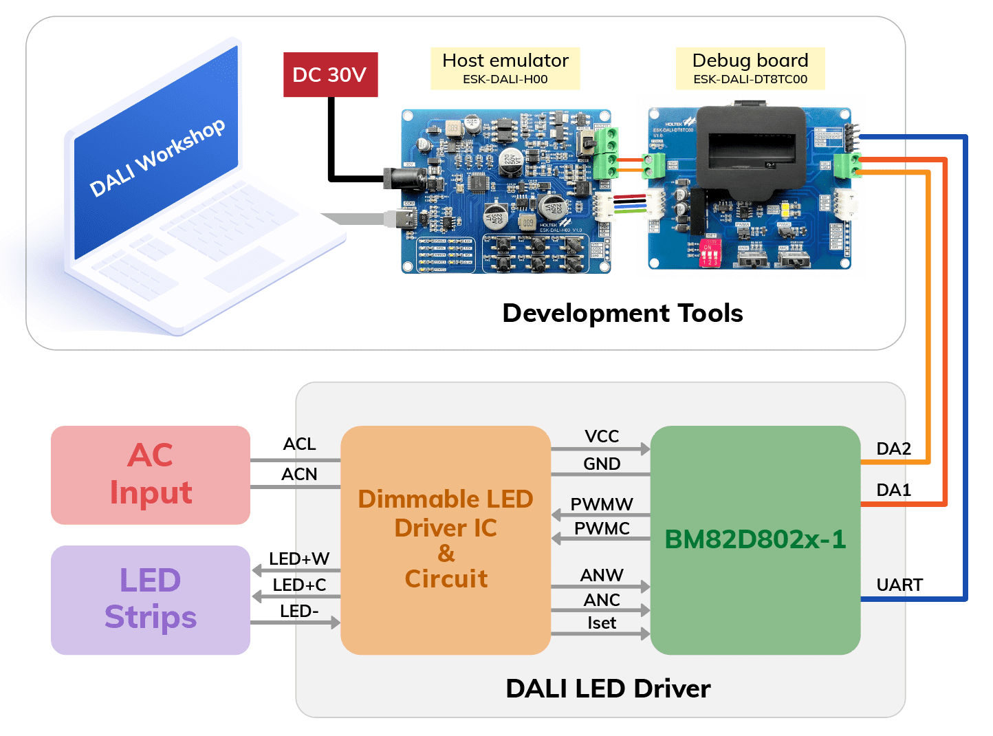
Furthermore, users don’t need to rewire the devices when they require changing lighting schemes or rearranging groups. It is highly convenient! We provide the development platform, DALI Workshop, to help users easily design products that comply with the DALI protocol.
In the DALI Workshop, users can assign addresses to each device and organize groups. Various parameters can be configured in the platform, such as dimming curve, fast fade time, color type, color temperature configuration, color scene, and more, helping you create ideal lighting effects.
Moreover, users can also monitor the current status of devices in the platform and generate program code for secondary development uses.
Require materials
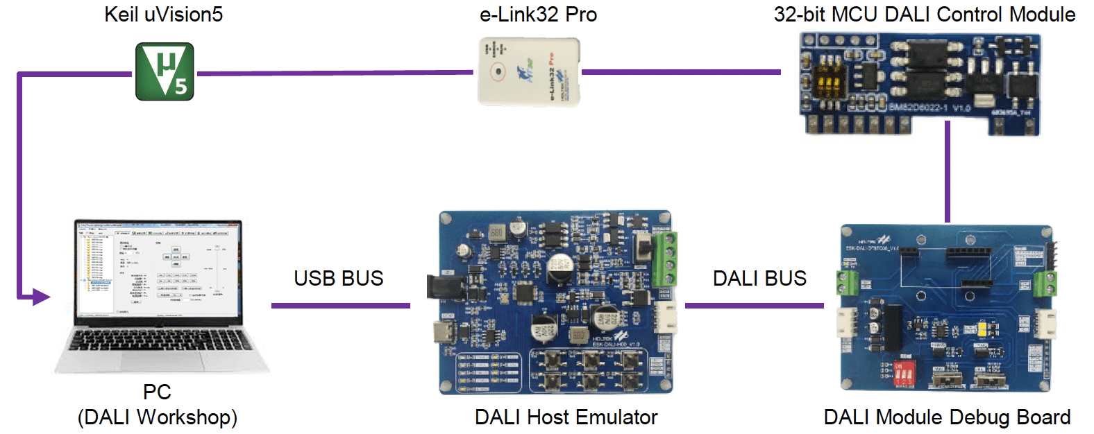
⬥ Software: DALI Workshop, Keil uVision5
⬥ Tool: BM82D8022-1, e-Link32 Pro, Module debug board ESK-DALI-DT8TC00, Host emulator ESK-DALI-H00.


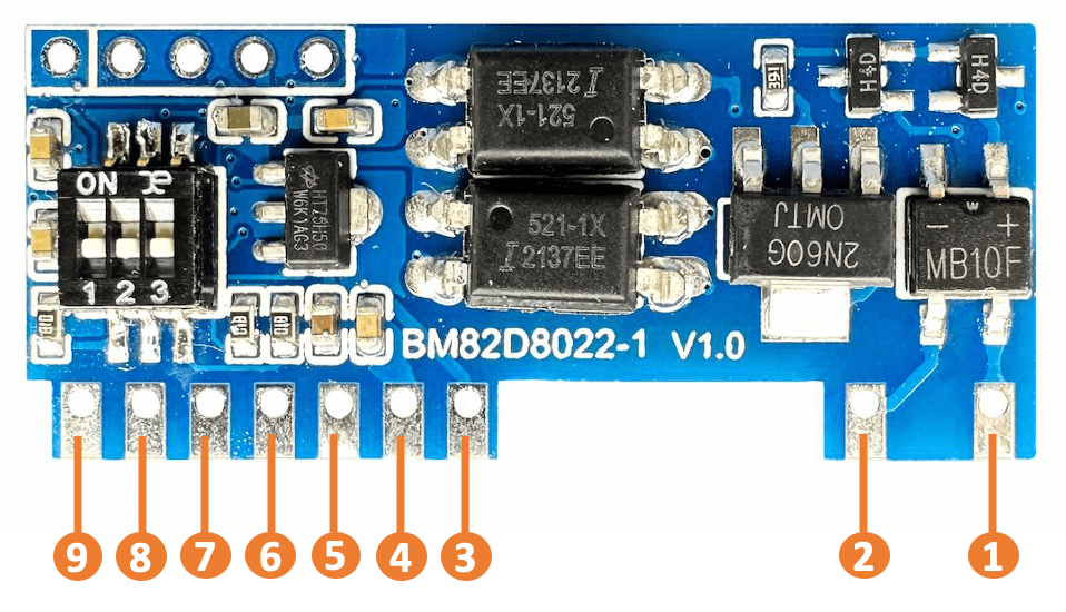
| Pin | Pin name | Function |
|---|---|---|
| 1 | DA1 | DALI interface |
| 2 | DA2 | DALI interface |
| 3 | VCC | Power supply: 7V~30V |
| 4 | GND | Ground |
| 5 | PWMW | PWM output pin (warm color) Push-pull output, high active |
| 6 | PWMC | PWM output pin (cool color) Push-pull output, high active |
| 7 | ANW | Fault detection pin (warm color) with an internal 10kΩ pull-down resistor |
| 8 | ANC | Fault detection pin (cool color) with an internal 10kΩ pull-down resistor |
| 9 | Iset | Current limit level detection pin |
- The ANW and ANC pins are fault detection pins that can detect whether the LED is in a fault status by inputting voltage and measuring it with the ADC.
- Both the Iset pin and DIP switch can be used to control the PWM output ratio (brightness). Its default min. brightness is 1%.
Once the Iset pin is soldered with external resistors, it has higher priority for PWM output ratio control and the module’s DIP switch control will be invalid.
It is recommended to use a 3-bit DIP switch and three resistors on the driver for selecting Iset level.
The DIP resistance values are SW1=56kΩ, SW2=30kΩ and SW3=16kΩ.
| BM82D8011-1 | BM82D8021-1 | BM82D8022-1 | |
|---|---|---|---|
| Supported device type | DT6 | DT6 & DT8(Tc) | DT6 & DT8(Tc) |
| Compliant standard | 101/102/207 | 101/102/207/209 | 101/102/207/209 |
| Operating voltage | 7V~30V | 7V~30V | 7V~30V |
| DALI interface voltage | 9.5V~22.5V | 9.5V~22.5V | 9.5V~22.5V |
| DALI interface withstand voltage |
260V AC | 260V AC | 260V AC |
| Storage temperature | -40℃~125℃ | -40℃~125℃ | -40℃~125℃ |
| Ambient temperature | -25℃~85℃ | -25℃~85℃ | -25℃~85℃ |
| Brightness range | 0%~100% | 0%~100% | 0%~100% |
| PWM resolution | 0.1% | 0.1% | 0.1% |
| MCU | HT66F31A5 | HT66F2362 | HT32F50241 |
| ROM size | 16KW | 16KW | 64KB |
| Secondary development supported |
O | X | O |
| ROM size occupied by default settings |
64% | 98% | 46% |
- Development platform: DALI Workshop, including user’s guide, software.
- MCU: HT32F50241, 32-Bit Arm® Cortex®-M0+ MCU, including datasheet, package information, etc.
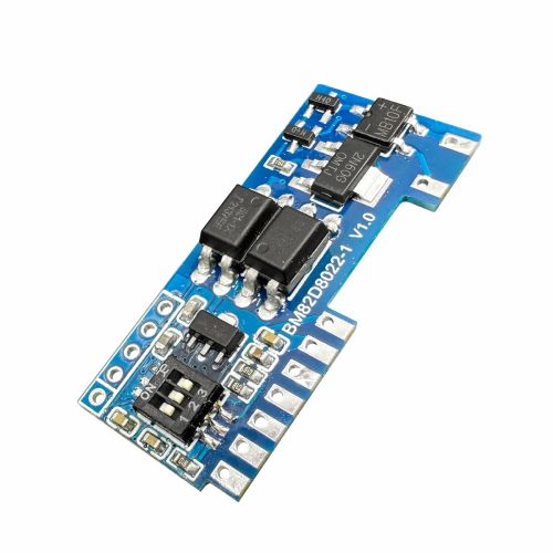
- Module: BM82D8022-1, DALI DT6/DT8(Tc) Control Module.


Reviews
There are no reviews yet.