
Description
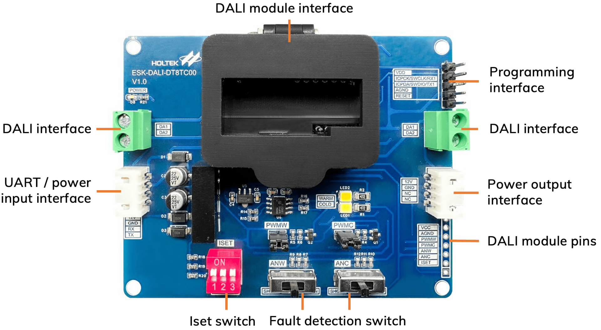
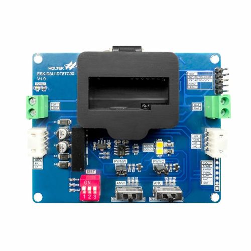
- UART/Power Input Interface: supplies 12V power from the host simulator board, ESK-DALI-H00
- Pull-out VCC Pin of DALI Module: 7~30V
The interface is designed for on-chip debugging and in-circuit programming (ICP).
The BM82D8021-1 and BM82D8022-1 support on-chip debugging. However, the MCU used in the BM82D8011-1 does not have the OCDSDA and OCDSCK pins, so it does not support on-chip debugging.
Debugging
- BM82D8021-1: e-LinkPro2/e-Link and HT-IDE3000 software
- BM82D8022-1: e-Link32 Pro and Keil uVision5 software
In-circuit programming
- BM82D8021-1 & BM82D8021-1: e-LinkPro2/e-Link and HOPE3000 for e-Link software
- BM82D8022-1: e-Link32 Pro and e-Link32 Pro ICP Tool software
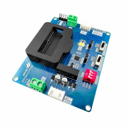
The PWM output level (brightness) is controlled by the external DIP switch and resistors connected to the Iset pin.
It is used to simulate the fault signal detected from the DALI LED driver control module.
The switch can simulate three different states:
- OPEN: simulate open-circuit fault signals
- SHORT: simulate short-circuit fault signals
- NORMAL: normal state
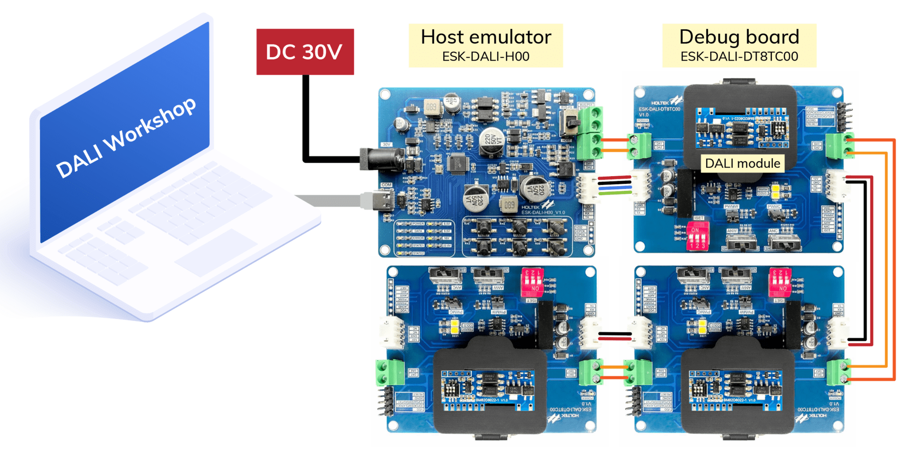
Steps for cascading DALI LED driver control modules:
- Connecting the UART/power output interface of the host simulator board ESK-DALI-H00 to the UART/power input interface of the product.
- Modules can be cascaded through both the DALI interface and the power output/input interface of the product.
⬥Refer to the diagram in the ‘Wiring’ section below for more information.
You only need one ESK-DALI-H00 to cascade multiple DALI LED driver control modules.
Please refer to the following wiring diagram, where we cascade 3 modules through the product, and power is supplied from the DC jack.
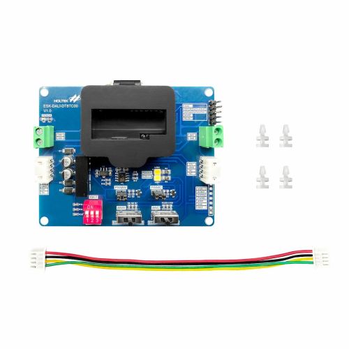
- Dimension: 95 x 75 x 18mm
- Net weight: 53.6g
- Product includes: ESK-DALI-H00 x1| Nylon post x4 | 4-pin cable x1
- Development platform: DALI Workshop, including user’s guide, software.


Reviews
There are no reviews yet.